

AIMA-EDFA
Erbium Doped Fiber Amplifier
 EDFA Datasheet
| EDFA Firmware | ||
| FW Part No. | Model | Version |
| S09144 | EDFA-G Single Pump |  V01.00.06 V01.00.06 |
| S08626 | EDFA-P Single Pump | V01.00.04 |
| S08751 | EDFA-P Double Pump | V01.00.03 |
| S10191 | EDFA-P-Comment | V01.00.01 |
Check FW Part No. of your EDFA module in ASMM Web UI
-> Modules -> Module Information -> FW Part No.
and download the correspondent firmware.
EDFA FBC Moudle Firmware V01.00.03
* For EDFA-M, please download the firmware of EDFA and
the one of EDFA FBC module.
* Login required for all downloads
About the Product
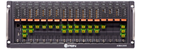
The Erbium Doped Fiber Amplifier (EDFA) is designed to plug into PBN's latest generation Advanced Intelligent Multi-services Access platform - the AIMA3000.
PBN's AIMA3000 EDFA module works in conjunction with 1550 nm optical transmitter modules to meet client requirements for different environments and transmission distances.
The EDFA employs a highly reliable pump laser with an advanced design to ensure that the unit can achieve a very low noise profile and high pump efficiency. The unit uses single or dual-pump lasers designed with inter-stage isolators. Its output power ranges from 13 dBm (19.95 mW) to 24 dBm (251.18 mW). The EDFA supports a fixed gain setting for dense wave division multiplexing (DWDM) applications as well as a number of user-selectable output ports.
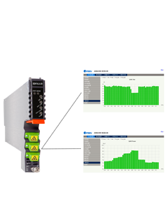
With the optional embedded Full Band Capture (FBC) module, it enables the operator to capture and monitor the spectrum and QAM demodulation data, including level of each channel, SNR, MER, BER, constellation and so on. Operators can get the metric of each QAM channel remotely.
The EDFA can also be conveniently monitored and controlled through a computer connected to one of the Ethernet ports or an Android mobile device via the ASMM module.
|
|
| Optical Performance | ||||
| Parameters | Min | Typ | Max | Unit |
| Optical Wavelength | 1530 | 1550 | 1565 | nm |
| Input Power (for A-EDFA-x-x-P-x) |
-6 | 0 | +10 | dBm |
| Input Power (for A-EDFA-x-x-G-x) |
0 | 11 | 14 | dBm |
| Number of Outputs | 1 | --- | 8 | pcs |
| Saturated Output Power (total power) |
13 | --- | 29 | dBm |
| Adjustable Range of Output Power (for A-EDFA-x-x-P-x only) |
-3 | --- | 0 | dBm |
| Output Power Stability (input variable) |
-0.5 | --- | +0.5 | dBm |
|
Output Consistency |
-0.5 | --- | +0.5 | dBm |
| Gain | --- | 20 | --- | dB |
| NF @ 0dBm Input | --- | --- | 5 (1) 6 (2) |
dB |
| Input Isolation | 30 | --- | --- | dB |
| Output Isolation | 30 | --- | --- | dB |
| Input Pump Leakage | --- | --- | -35 | dBm |
| Output Pump Leakage | --- | --- | -45 | dBm |
| Residual Pump Power (970 ~ 980 nm) |
--- | --- | -30 | dBm |
| Return Loss | 50 | --- | --- | dB |
| Polarization Dependent Gain | --- | --- | 0.3 | dB |
| Polarization Mode Dispersion | --- | --- | 0.5 | ps |
| Multi-wavelength Gain Flatness (for A-EDFA-x-x-G-x only) |
± 0.5 dB (1548 ~ 1562 nm) (3) ± 0.75 dB (1536 ~ 1562 nm) (3) |
|||
| Optical Connector | SC/APC, LC/APC, FC/APC, E2000/APC | |||
| RF Performance | |
| RF Test Point Output Power (4) | 15 dBmV ± 1 dB |
| General | |
|
Power Consumption
|
Total power less than 24 dBm < 20.0 W Total power less than 29 dBm < 25 W |
| Power Consumption of FBC Module | < 8 W |
| Operating Temperature | -5 °C to 55 °C |
| Storage Temperature | -25 °C to 70 °C |
| Operating Humidity | 90% (non-condensable) |
| Storage Humidity | 90% (non-condensable) |
| Dimensions (WxDxH) | 24.6 x 410 x 152.5 mm |
| Weight | 0.95 kg |
| Supported Network Management Options | PBN's NMSE or through ASMM's Web Interface |
| With the FBC Module | |
| Frequency Capture Range | 45 to 1000 MHz |
| Demodulation Mode | QAM 64, QAM 256 |
| Metrics and Functions Available | Level, SNR, MER, BER and live spectrum |
Note:
(1) Total output power < 25 dBm.
(2) Total output power ≥ 25 dBm.
(3) The recommended input power for an A-EDFA-1-17-G-S with 11 dBm optical input with a 6 dB gain typically has an output of 17 dB.
(4) Measured @ 3.2% OMI, 0dBm input, saturated output. Please note it is meaningful only when it was used to see its own changes over time or compare with adjacent devices.
| A-EDFA-[V]-[W]-[X]-[Y]-[Z] | Erbium Doped Fiber Amplifier |
| Options | |
| V |
FBC Function (1) |
| M | With FBC Management |
| W |
Output Ports Number |
|
1 2 4 6 8 |
1 port 2 ports 4 ports 6 ports 8 ports |
| X |
Power per Port (2) |
|
13 14 15 ~24 |
13 dBm 14 dBm 15 dBm ~ 24 dBm |
| Y |
Working Mode |
|
P G |
Constant Power Constant Gain |
| Z |
Connector Type of Output Ports (3) |
|
S E F L |
SC/APC E2000/APC FC/APC LC/APC |
| Examples | |
| A-EDFA-1-20-P-S | AIMA3000 1-Slot EDFA Module, 1 output port, 20 dBm each, Constant Power, SC/APC connector |
| A-EDFA-2-15-G-E | AIMA3000 1-Slot EDFA Module, 2 output ports, 15 dB constant gain, E2000/APC connector |
| A-EDFA-M-4-16-P-L | AIMA3000 1-Slot EDFA Module, FBC, 4 output ports, 16 dBm each, Constant Power, LC/APC connector |
| A-EDFA-6-13-P-L | AIMA3000 1-Slot EDFA Module, 6 output ports, 13 dBm each, Constant Power, LC/APC connector |
Notes:
(1) Option for FBC management configurations only. please omit [X] when select a model without FBC function. Not available for constant gain models.
(2) Maximum output power per port for different outputs at constant power, constant power with FBC or constant gain situations:
| Output Number | Constant Power | Constant Power with FBC | Constant Gain |
| 1 | 24 | 23 | 24 |
| 2 | 21 | 20 | 20 |
| 4 | 21 | 17 | 17 |
| 6 | 21 | 15 | 15 |
| 8 | 20 | 14 | 14 |
(3) Available connector type for different outputs:
| Output Number | Available Connector Type |
| 1 | SC/APC, LC/APC, FC/APC, E2000/APC |
| 2 | SC/APC, LC/APC, FC/APC, E2000/APC |
| 4 | LC/APC |
| 6 | LC/APC |
| 8 | LC/APC |